Understanding Injection / Sampling DBB Valves with Probe & Support Collar Application
Based on the blog post “Chemical Injection Quill for Oil & Gas” written by my colleague Kevin Alamag, I would like to dive more into the depth of the application fields of Injection / Sampling DBB Valves.
In my course of work talking to OEMs, EPCs, end-users and other clients on this injection/sampling area, I was surprised to know that there are many misunderstandings on this small but important product range within the whole process.
Within our AS-Schneider product range, an injection or sampling probe comes in combination with a double block and bleed valve as a one complete product. As the name suggest, injection is used when adding additives into the media in the pipeline, to produce a product according to end user specification. As for sampling, purpose is to draw media out from a pipeline, and this media will be use as sample, that will be sent to a lab, to check if the sample drawn from this sector is within the product parameters.
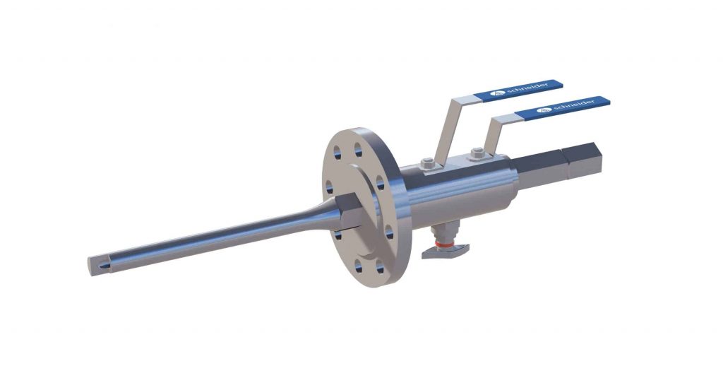
Injection DBB with check valve
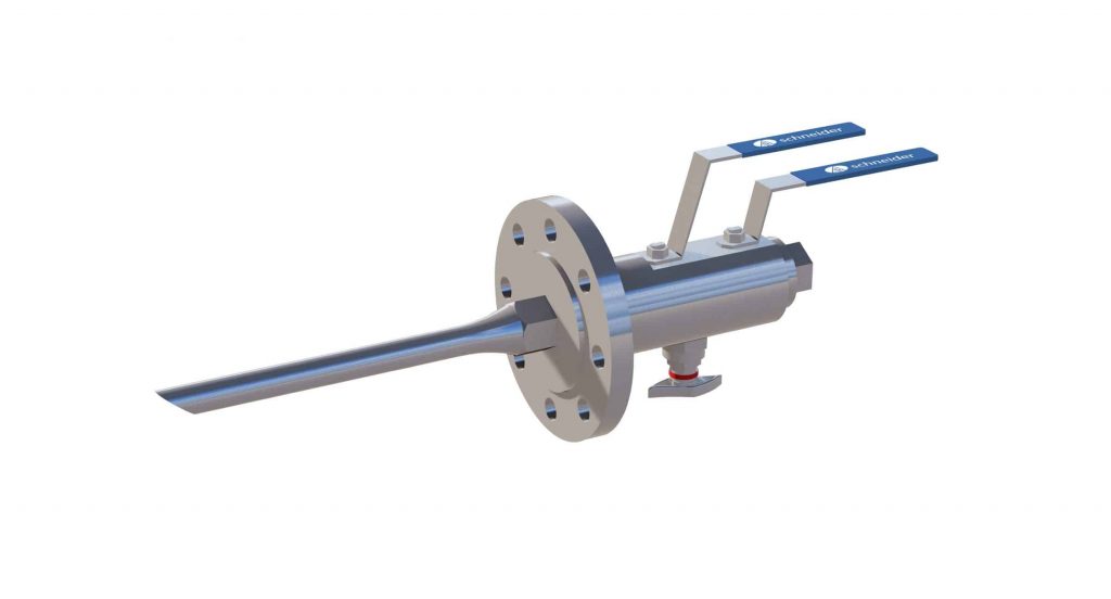
Sampling DBB
Having an inserted item into a pipeline can proved to be disastrous if its not designed correctly. Take for instance, in 1995, a serious incident happened when a thermowell broke off in the pipeline at Monju Nuclear Powerplant in Japan. It came perilously close to causing an explosion that could have caused a radiation leak.
Manufacturers need to take a serious view when performing the Wake Frequency Calculation, to check if the probe length require is suitable according to the flow parameters given by the end user.
According to process engineers, general rule of thumb on how much length to be immersed in the pipeline is as follows:
Injection probe needs to be insertedto the center of the pipeline;
Samplingprobe needs to be inserted to 1/3 of the pipeline diameter
When the Wake Frequency calculation result indicates that the length require is not optimal due to the material and dimension of the probe combined with the flow parameters (for example velocity and viscosity), a support collar might be able to improve the situation.
So how does this process goes…
Injection / Sampling DBB with probe
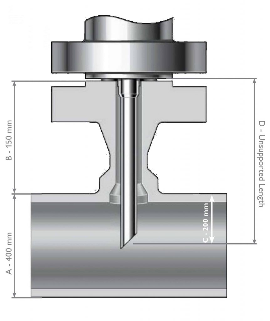
Example: Refer illustration 1, an injection DBB with probe needs to be inserted ½ way into a pipeline of “A” at 400 mm diameter, to achieve having the probe tip position in the middle of the pipeline at “C” 200mm, probe length “D” needs to be 350 mm. This overall length “D” is considered as “Unsupported Length”.
After Wake Frequency Calculation, if result shows maximum Unsupported Length is 300 mm instead of required 350 mm, a support collar will need to be added on to achieve length require by user.
Illustration 1
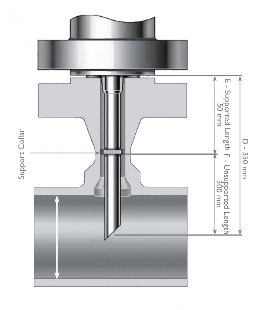
Illustration 2
*** above illustration not to scale
Refer illustration 2, a support collar is set at 50 mm away from flange of DBB , this portion “E” is now consider as Supported Length, and “F” will be Unsupported Length of 300 mm, calculation starts from support collar onwards to the end of the probe.
With Unsupported Length of probe at 300 mm now, it falls within the Wake Frequency result recommendation, and overall length of the probe of 350 mm can be used as required.
Support collar application
The purpose of adding support collar is to achieve the probe length according to end user requirement, for maximum insertion into the pipeline. The goal is also ensuring that the Unsupported Length of the probe, will be within the Wake Frequency Calculation tolerance limits.
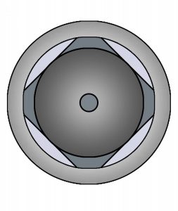
From AS-Schneider, our injection/sampling DBB probe that comes with support collar, are manufactured in a 4-point form.
4-point collar (top view)
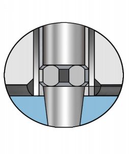
Support collar (internal view)
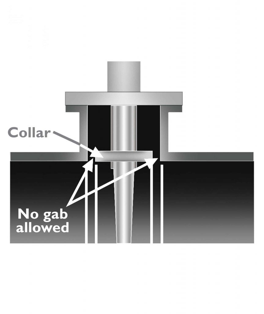
The optimal way of installing an injection/sampling DBB with probe and collar, has always been a controversial topic. First of all, in order for the support collar to serve its purpose, it needs to be fitted tightly within the flangeolet. Any gaps between the support collar and flangeolet wall will cause failure over time due to de-formation of collar caused by vibration.
From AS-Schneider, recommendation is to produce a support collar that is approximately 1-2 mm more than the given diameter of the flangeolet. On site, installers will position the injection/sampling DBB valve on top of the flangeolet, shave some material off the 4-point collar equally, in order to have the support collar achieving the tightest possible fit within the flangeolet.
After thoughts
According to standard ASME PTC 19.3TW-2010, (though it’s meant more towards thermowell, it can also apply to injection/sampling DBB with probe) there is a paragraph specially addresses the use of support collars:
Support collars or other means of support are outside the scope of the standard. The use of support collars is not generally recommended, as rigid support can only be obtained with an interference fit between the support collar and the installed piping… Such designs require methods beyond the scope of this standard.
As such, users should always consider some of the following options, which could be better means against failures:
Reducing the immersion probe length into the pipeline
Reducing the height of flangeolet to reduce overall Unsupported Length of probe
Achieving maximum probe diameter of injection/sampling DBB valves
Installing the injection/sampling DBB with probe after an angle or elbow of a pipe
For any further information or discussion, please do contact any of our AS-Schneider specialist.