Practical test installation of a DBB Piping Ball Valve at a gas storage facility
One of the things that I enjoy the most about my job is discussing new improvement opportunities with clients. Situations like that push me to engineer viable solutions that solve operational setbacks, so they can enjoy more reliability and safety at work. And that was what happened when I designed the practical test installation procedure I’m about to share. It was for a double block and bleed (DBB) ball valve installed in a gas storage facility.
Paving the way for new solutions
While doing a routine checkup at a German natural gas storage facility, the maintenance supervisor shared with me his great aspiration of seeing all bypass lines modernized. At the time, he was still unsure about the right valve solution for the facility. Yet, he was well informed on the financial commitment implied. The stakes were high. Valves would need to be a perfect fit for his plans to be greenlighted. And not only for safety and supply chain reasons but also to justify the investment.
As days passed, our conversation did not leave my mind, even though I was already taking on other duties. I wanted to support my customer’s goal by envisioning how AS-Schneider could embrace this challenge as a service partner.
Then, unexpectedly, over a delicious plate of “Kieler Sprotten” (German smoked fish) – which I highly recommend to anyone visiting northern Germany-, I found a proposal to share with my customer. A test plan that could get his plans rolling. He was enthusiastic about it.
Test design
After thoroughly detailed exchanges with my natural gas storage customer, we jointly decided that a field test with a DBB piping ball valve under real conditions would be useful.
We worked together to define the following key data for the practical test:
Valve specifications:
To begin with, the valve had to meet these specifications:
- Bore Size: 2”
- Type: trunnion design
- Rate: DN 50 ANSI 1500 RTJ
- Design pressure: 230 bar
- Temperature range: -10°C to + 50°C with APZ 3.2
- Material: steel
Standard specifications:
Additionally, the valve had to comply with the following standards:
- Design: ASME B16.34, API 6D/ISO 14313, and ASME B31.3
- Flange dimensions: ASME B16.5
- NPT threads: ASME B1.20.1
- Valve pressure rating at ambient temperature: ASME B16.34
- Max. temperature: PEEK ball seats at 232°C
- Min. temperature: 29°C
- Fire safe: tested and approved according to ISO 10497/API 607
- All wetted parts: in compliance with NACE MR0175 and ISO 15156
- Flange dimensions (diameter, bolt holes, bolt circle, facing, flange thickness): ASME B16.5
- Factory testing: as per ASME B16.34, API 6D/ISO 14313, and ISO 5208
- Shell test: 1.5 x max. cold working pressure (water)
- Seat test: 1.1 x max. cold working pressure (water) + 6 bar test (air)
- Ball body and stem-body electrical resistance: 10 Ohm
- Weight: 92 kg approx.
Bypass installation settings and testing conditions:
We also defined the following bypass installation settings and testing conditions:
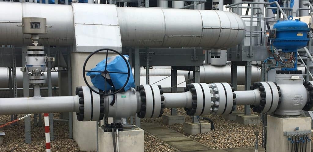
- Location: natural gas cooling bypass line (after the first compressor stage)
- Medium: dry natural gas
- Pressure: 145 - 200 bar
- Temperature: 20°C to 80°C
- Function: relief/purge valve
To avoid the extremely loud noise—typical of blowing natural gas above 100 bars into the atmosphere—we had no choice but to add a modification to the piping section. Therefore, we dismantle a short pipe section to mount a silencer directly on the outlet side of the DBB valve—prior to the DBB installation.
Test preparation procedure:
At last, we established the test preparation procedure. The test phase would last 12 months.
During this period, the DBB piping ball valve had to be regularly subject to a leakage test and performance follow-ups by the maintenance supervisor.
Test installation
Before starting, the proposal had to be presented to the maximum authorization levels at the natural gas storage facility for approval. Once greenlit, it was time to bring it to life.
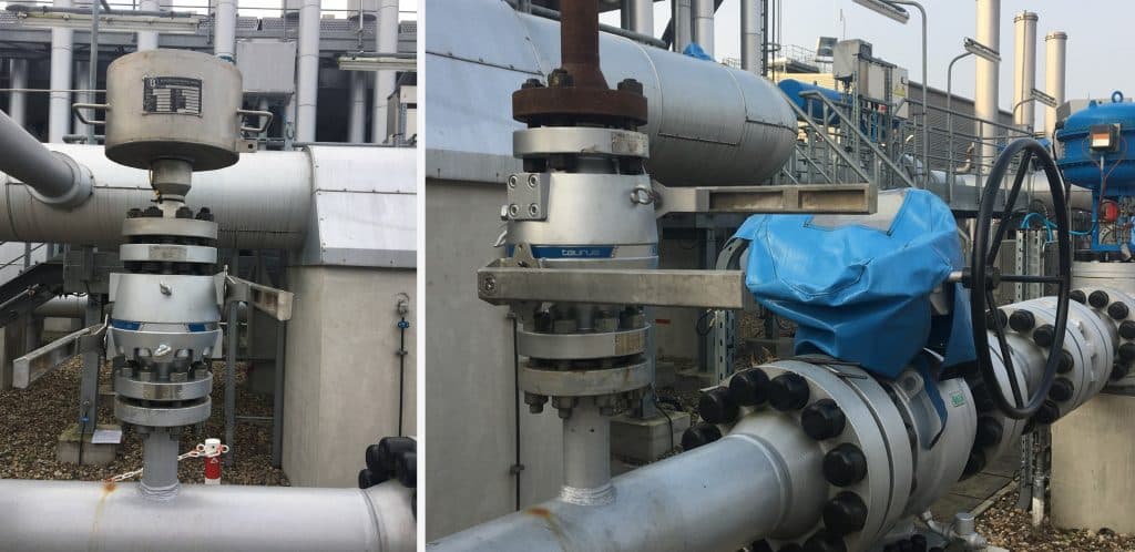
The installation consisted of installing the DBB piping ball valve in the bypass natural gas of the first compressor stage’s cooling line. The features specified during the test design stage were successfully met. The entire process lasted around 335 days. All the fieldwork was handled by the operator.
AS-Schneider was on site throughout the totality of the test installation. Our responsibility was to supply the DBB valve and provide the technical support necessary to ensure a seamless completion. For us, this experience went beyond lending our expertise in the field. It was also about building a long-term, trusting partnership with our client.

Start of practice operation
The operation phase for this trial lasted nearly one year. For overall consistency, we will share the results in two periods, start and end.
Every few weeks, the DBB valve underwent routine inspections while in operation so that a short blow-out could occur each time. The medium was dry gas at 160 bar. The tests took place at the original valve location. No issues ever surfaced that could jeopardize safety.
Still, as with any trial, there are positive and negative aspects to notice, whether to make amends or reinforce future installations.
Positives | Negatives | |||||||||||||||||||||||||||||||||||||||||||||||||||||||||||||||||||||||||||||||||||||||||
|---|---|---|---|---|---|---|---|---|---|---|---|---|---|---|---|---|---|---|---|---|---|---|---|---|---|---|---|---|---|---|---|---|---|---|---|---|---|---|---|---|---|---|---|---|---|---|---|---|---|---|---|---|---|---|---|---|---|---|---|---|---|---|---|---|---|---|---|---|---|---|---|---|---|---|---|---|---|---|---|---|---|---|---|---|---|---|---|---|---|---|
• Very compact design, two ball valves and one vent valve in only one body. | • The plug for intermediate pressure relief did not contain a relief hole for safety reasons. If pressure had built up after the bleed valve, unscrewing the plug would have been a dangerous operation. | |||||||||||||||||||||||||||||||||||||||||||||||||||||||||||||||||||||||||||||||||||||||||
• Short overall length. | ||||||||||||||||||||||||||||||||||||||||||||||||||||||||||||||||||||||||||||||||||||||||||
• No interfaces and therefore no leakage possibilities between the individual shut-offs. | ||||||||||||||||||||||||||||||||||||||||||||||||||||||||||||||||||||||||||||||||||||||||||
• Stable levers for actuation. | ||||||||||||||||||||||||||||||||||||||||||||||||||||||||||||||||||||||||||||||||||||||||||
• Valve tightness remained unaffected. | ||||||||||||||||||||||||||||||||||||||||||||||||||||||||||||||||||||||||||||||||||||||||||
End of practice operation
The DBB valve was removed, after almost one year of operation, during a regular shutdown of the entire natural gas storage plant. Performance-wise, the valve operated satisfactorily for the whole period.
What came next? Extensive tightness tests to verify the integrity of the dismantled DBB piping ball valve.

Tightness test results
The leakage tests were carried out at the customer’s premises. I supported the customer during each test run and helped to verify the results. As a loyal partner, my presence during the test was a priority for me.
The different tightness tests seek to verify:
- Outer tightness of the 2nd ball
- Inner tightness of 1st ball
- Vent tightness
- Tightness of both sides of the trunnion seal
The test environment included:
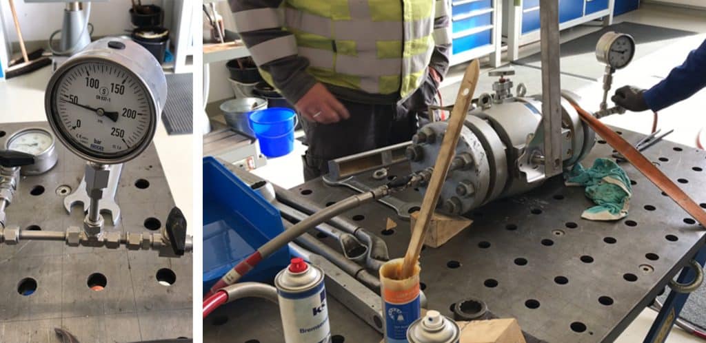
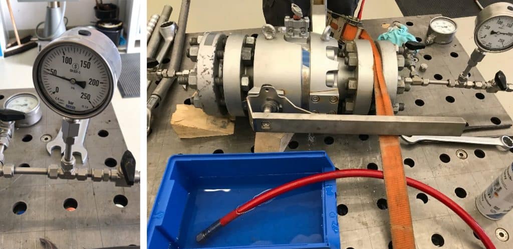
- The DBB pipeline ball valve was strapped to the workbench with a tension belt so that the hand lever could be operated safely.
- Test medium: air/nitrogen
- Inlet: flange with a screw connection, in front of it a pressure gauge and a ball valve shut-off valve.
- Outlet: ball valve with hose leading into a water tank.
- The test evaluation was done via bubble formation in the water tank.
Let’s go over the results!
Outer tightness test of the 2nd ball valve
For the outer tightness test, the 1st ball valve was opened, the 2nd ball valve was closed and the bleed valve was also closed. The applied pressure in the 2nd ball valve was 50 bar.
First result: a bubble formed.
I felt queasy in my stomach area, thinking the DBB piping ball valve was leaking. The maintenance supervisor, as calm as ever, told me to relax because a bubble formation could happen every now and then if the valve hasn’t been operated for a long time. So, we needed to depressurize the ball valve and open and close the 2nd ball with the hand lever several times to vent the dead space and then operate the ball again several times.
Afterwards, we repeated the test at 50 bar, and did other runs at 100 bar, 150 bar, and 200 bar.
Final result: no bubble formation, tight!

Inner tightness test of the 1st ball valve
For the inner tightness test, the 1st ball valve was closed, the 2nd ball valve was opened and the bleed valve was closed. The applied pressure was 50 bar, 100 bar, 150 bar and 200 bar.
First result: At 50 bar and 100 bar there were no bubble formation, bubble formation began at 150 bar (slight) and continued at 200 bar.
As noted above, also here the bubble formation at 200 bar was acceptable because the ball was not switched/actuated and under those conditions is usual to form bubbles.
Before repeating the test, we moved the ball and opened and closed it 10 times.
The leak test was done again, for all pressures (50 bar, 100 bar, 150 bar, and 200 bar).
Final result: no bubble formation, tight!

Further tightness tests
After checking the inner seal of the 1st ball valve, the outer seal of the 2nd ball valve, it was time to verify the trunnion seal and the vent seal. Here, too, the leakage test was convincing.
I have summarized all the relevant results for you in a table:
|
2nd ball outer tightness test |
1st ball inner tightness test |
Vent tightness test |
Trunnion tightness test |
|||||
|---|---|---|---|---|---|---|---|---|
| Applied pressure | 1. run | 2. run | 1. run | 2. run | 1. run | 2. run | 1. run | 2. run |
| 50 bar | Bubble formation | No bubble formation, tight | No bubble formation, tight | No bubble formation, tight | No bubble formation, tight | ** | Light bubble formation | No bubble formation, tight |
| 100 bar | ** | No bubble formation, tight | No bubble formation, tight | No bubble formation, tight | No bubble formation, tight | ** | Light bubble formation | No bubble formation, tight |
| 150 bar | ** | No bubble formation, tight | Slight bubble formation | No bubble formation, tight | Slight bubble formation | ** | Bubble formation | No bubble formation, tight |
| 200 bar | ** | No bubble formation, tight | Bubble formation | No bubble formation, tight | Slight bubble formation | ** | Strong bubble formation | No bubble formation, tight |
**: not conducted.
Our natural gas storage customer was pleased with the results and looking forward to the next phase of testing.
Additional tightness tests in TechCenter
The next test should be a visual inspection of the balls and the sealing surfaces, whereby the DBB piping ball valve must be disassembled and unscrewed. Due to special tools required, this test will take place in our own test laboratory at AS-Schneider headquarters in Nordheim (Germany). I will keep you posted once it is completed.
My outro
I’m really proud of the work accomplished alongside my natural gas storage customer. We developed a practical test installation for a DBB piping ball valve suitable for high pressure applications. The trial process took us nearly a year to complete. And the results proved that the methodology designed was effective at preserving valve tightness. In some cases, without even having to actuate the valve. Thus, I seriously recommend you do.
For us at AS-Schneider, this project was special from beginning to end. It introduced us to an opportunity to collaborate on a direct basis with our client, allowing us to deliver more than our field expertise. This time, we were partners to be trusted. So, our focus centered on dismissing the sleepless nights that often come with operational issues by presenting doable solutions.
Who knew how far would progress an idea first had over one of Germany’s finest and most traditional meals?
Until next time!
Image Source: © AS-Schneider

