What is a valve manifold and where are valve manifolds used?
Valve manifolds are flow management devices of ever-growing interest for operators, maintainers, and design teams worldwide. Even under today’s landscape of ongoing innovations, they continue to be a go-to technical solution for fluid control in systems. When two or more valves are involved, that is.
Since their deployment extends across diverse processes in several industries, it is only fitting to seize the opportunity to offer knowledge on them.
What are valve manifolds? When to use them? What configurations are available?
These are some of the questions to address in this introduction feature. Please, continue reading below to get the details.
What is a valve manifold? How does it work?
Oftentimes comes an industrial application that calls for the setup of various valves in practically the same location. Such a specific requirement obeys a tailored configuration prepared to achieve the desired design and measurement targets.
There are two options to tackle this process demand.
The first one is through the arrangement of a set of individual valves. A proposal that can get the job done, carrying many disadvantages to its credit. For instance, it is pricey to install and maintain. And it requires a large and bulky structure that takes up a lot of space and leaves room for many potential leak paths.
The second possibility is much simpler and overall preferred. It’s the installation of a manifold. A valve manifolds!
A manifold is a system that combines multiple valves into a single unit. A bridge between the instrument and the process. A piping segment where, internally, the valves connect in standard configurations given by a design engineer.
The manifold is carefully assembled to allow the calibration or replacement of measuring instruments in total safety. Without having to shut down the plant! For that reason, there are different configurations available, fit for various applications.
Given how beneficial they are, valve manifolds write individual installations off the table from the get-go.
What are the uses of valve manifolds?
Valve manifolds fulfill critical operational functions, including:
- Blocking a connection to the process
- Equalizing pressure between the two ports of the measuring device
- Bleeding the segment between the instrument and the process
Because of their versatility, manifolds are a common fixture in oil & gas, petrochemical, chemical, power generation, and water and wastewater facilities. Signs are that if you are a fluid control operator for any of those industries, you have encountered a manifold along the way.
What process variables are up for measurement in valve manifolds?
Four major process variables are up for measurement in manifolds. They are:
- Pressure (gauge and differential)
- Flow rate
- Fluid level
- Temperature
Each of these variables belong to an applied measuring instrument.
Since pressure is the most monitored variable in manifolds, it’s crucial to state the differences between the two possible reads, gauge pressure and differential pressure.
Gauge pressure
Gauge pressure is the pressure of a system above atmospheric pressure. The value measured is zero-referenced against ambient air (or atmospheric pressure). The reading ultimately includes the pressure from the weight of the atmosphere.
Differential pressure
As the name suggests, differential pressure (DP) is the difference in pressure between two given points. Its value also serves as the basis to estimate other variables, such as flow rate, fluid level, viscosity, density, and temperature. Fluctuations in differential pressure tend to indicate that there’s a potential problem in the process line.
What are the different configurations of valve manifolds?
There are several design configurations available for valve manifolds. Each applies the same principle of incorporating multiple valves into a single body.
The manifold, as meant by design, is built-in with several ports that enable connections to the process, the measuring instrument, or other devices for calibration. The number and types of valves per unit are dependent on the manifold’s functionality. At the moment, there are three types of valve manifolds:
2-valve manifold
A 2-valve manifold consists of a block valve and a bleed or test valve. And it offers the same functionality as a block and bleed valve.
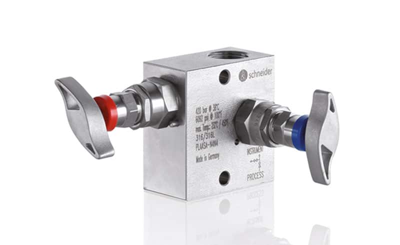
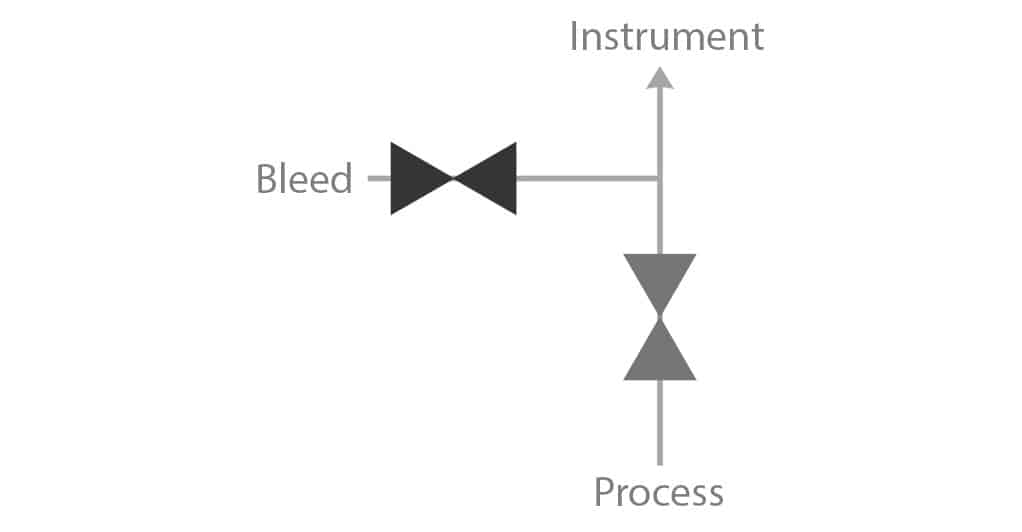
Operational considerations of a 2-valve manifold
- The bleed valve is kept closed during normal operation.
- To calibrate the pressure transmitter, the block valve is closed and the bleed or test valve is open.
- The test valve is connected to a pressure generator to test the instrument.
- The block valve permits isolating the pressure transmitter from the process.
- Pressure is vented using the bleed valve after which the instrument can be removed for service or repair.
- The arrangement is usually followed by a pressure gauge, a pressure transmitter, or a pressure switch. It cannot be used with differential pressure transmitters as there is only one port available for the process connection.
3-valve manifold
A 3-valve manifold consists of two block valves and an equalizer valve. And is used with differential pressure transmitters to prevent instrument over-range. Also, to allow isolation of the transmitter from the process line during maintenance and calibration.
A 3-valve manifold has at least four ports. Two are connected to the DP transmitter itself. The remaining two ports connect to the process locations to measure the DP.
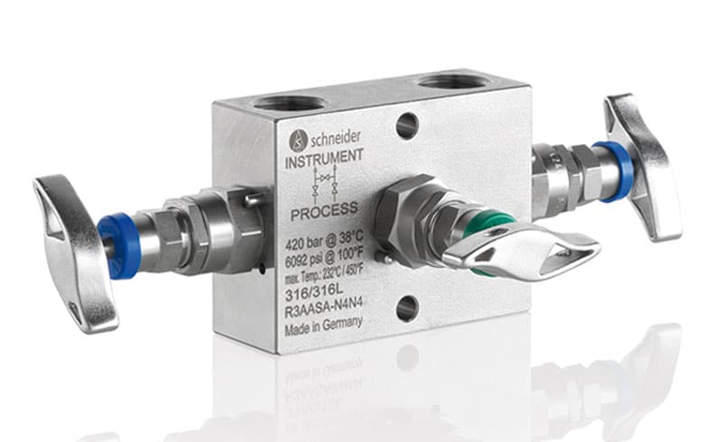
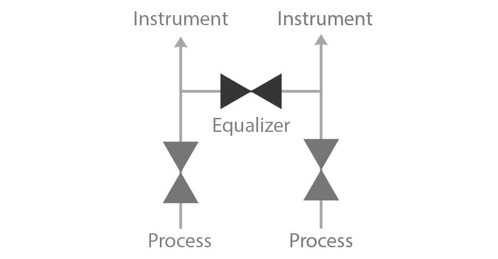
Operational considerations of a 3-valve manifold
- On normal operation, the equalizer valves are kept tightly closed and the block valves remain open.
- Zero readings in the DP transmitter can be easily verified by equalizing the pressure on the two sensor diaphragms. To do this, the block valves must be closed and the equalizer valve opened.
- The standard procedure for instrument removal due to service or repair is to close the high-pressure valve, open the equalizing valve, and finally close the low-pressure valve.
- It does not provide a test connection. For that reason, it is rarely used in the oil and gas industries.
- Some manufacturers offer a modified version with test ports, but in general, a test connection is not available.
- It does not support a built-in option to bleed the trapped fluid pressure into the atmosphere. Installation of an extra bleed valve is required to vent the trapped fluid pressure.
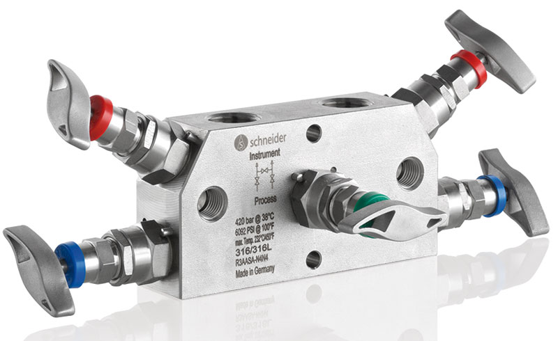
5-valve manifold
5-valve manifolds are the most commonly used manifolds for differential pressure transmitter applications (measurement).
The 5-valve manifold consists of two block valves and one equalizer valve. Plus, two additional valves for venting or testing.
In addition, a 5-valve manifold provides the ability to block, equalize, and vent two process connections along with the option of calibrating the transmitter without removing it from the setup.
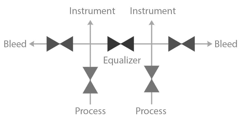
Operational considerations of a 5-valve manifold
- For differential pressure measurement, block valves are kept in the open position with the equalizer and bleed valves tightly closed.
- During calibration, the block valves are closed, and the equalizing valve is opened to check the zero of the pressure-transmitter. After the pressure has equalized, the equalizer valve will be closed and the test valves or vent valves of the manifold are connected to a pressure generator for three or five-point calibration.
- Vent valves release the pressure into the atmosphere before the instrument is removed for service or repairs.
- It is utterly important to ensure that the equalizing valves are never opened while the two block valves connected to the process are open. Otherwise, it can cause for the process fluid to flow through the equalizing valves from the high-pressure to the low-pressure side.
What kind of body styles of valve manifolds are available?
Valve manifolds are available in two major body styles: Horizontal body style and vertical body style.
The basic difference between the two is the orientation of the main body of the manifold. But when to pick one over the other? The choice of style depends on the available space and the process layout.
Horizontal body style
Vertical body style
Example of horizontal body style
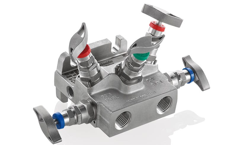
The main body of the manifold is horizontal with connecting ports on the smaller face.
Example of vertical body style
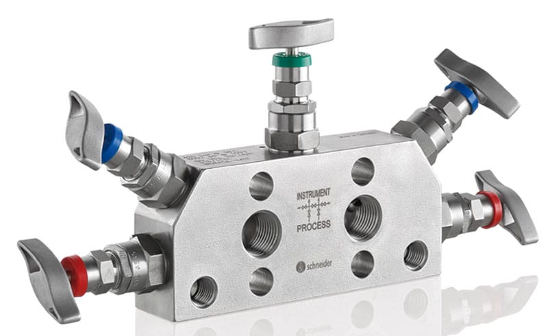
The main body of the manifold is vertical with connecting ports on the larger face.
What kind of mounting styles of valve manifolds are available?
Valve manifolds can be mounted using two different styles, direct mounting or remote mounting.
Direct mounting
The direct mounting style connects the pressure instruments straight to the manifold. To do so, a combination of flange and threaded connections are in use.
There are some highly appreciated benefits to this style. For instance, it improves energy efficiency by shortening system flow paths. The pressure drop reduces and heat loss goes to a minimum. Other advantages are:
- Lower installation cost
- Simpler maintenance
- Fewer potential leak points
- Full system support on hard pipes
Remote mounting
In remote mounting, the manifold’s installation is done away from the instruments. The linking is possible thanks to the use of threaded connections only.
There is a plus side to remote mounted valve manifolds:
- Increases the instrument's protection from extreme process temperatures.
- Eases the installation process using tubing and tube fittings.
- Grants the deployment of standard instrument manifolds.
Typical features of a valve manifold
An extensive line from several manufacturers of valve manifolds for pressure and differential pressure gauges exists in the market. To facilitate the selection process for you, here are some of the desirable features to look for:
- One-piece single body design
- Bubble tight shut off valves to ensure leakage free performance and functional safety
- Non-rotating needle for smooth operation and minimum wear of sealing elements
- S-bar valve handles for ease of operation ergonomic handle design for ease of operation
- Valve seat options: Metal to Metal, Soft Tip PCTFE or POM
- Metal to Metal back seat to release packing stress, increasing its lifespan
- Stem threads that are protected from process media to prevent galling
- Cold rolled stem threads for increased wear and fatigue resistance
- Blow-out proof needle
- Lock pin to prevent unauthorized removal of the bonnet
- Anti-tamper valve head design to prevent unauthorized opening and closing of the valve
- Color coded dust cap for operating thread protection and functional identification
- High working pressure range of up to 420 bar (6.092 psi)
- Panel mount design
- Gland packing to provide maximum sealing with minimum air adjustment
- Body material choices include carbon steel or stainless steel
- Standardized center distances of 37 mm and 54 mm for commonly used process transmitters
- Carbon filled PTFE packing for TA-Luft compliance
- Special body material choices from Duplex to Super Duplex and Alloy 400 to Alloy C-276
- Valve bonnet with replaceable bonnet sealing washer arrangement
- Compliance with industry standards for prevention of fugitive emission, sour gas service and oxygen service.
Advantages of using a valve manifold
Operators have a lot to gain from valve manifolds. Even more so when comparing them to the arrangement of individual valves. Characteristics like the small space needs and the high reliability throughout the installation, operations, and maintenance phases go a long way. They create staggering qualities hard to ignore. So, let’s summarize them into these advantages for everyone to know:
- Reduced chances of leakage due to fewer connections and joints.
- Less installation costs thanks to the compact size, which requires fewer fluid connections.
- Complete assembly is fully pressure tested.
- Reduced time for installation and maintenance.
- Compact size fit for installations in confined spaces.
- Availability in several designs for use in instrument, remote-mount, direct-mount, and module systems.
- Improved layout with fewer hoses and connections.
- Simplified operations.
- Shorter flow path, helping reduce pressure drop and heat loss, thereby improving the overall efficiency.
- Increased reliability and enhanced operator safety.
Summary
To wrap up, we want to leave you with a summarized context of what we just shared on valve manifolds. So that you can make a better selection as a designer or operator.
Valve manifolds are devices that bring great flexibility, safety, and reliability to fluid control operations. Their clever design pushes forward the operator’s capabilities in a wide setting of scenarios, making it possible to test, vent, block, or bleed process lines without shut down.
But that’s not it!
They also simplify core aspects of process variable measurement, enhancing the gathering of pressure (gauge and differential), flow rate, level, and temperature data. All that while reducing to a minimum the chances of fluid leakage along the path.
Their high functionality is due to the specificity of the different models available:
✓ 2-valve manifold
✓ 3-valve manifold
✓ 5-valve manifold
✓ Horizontal body style
✓ Vertical body style
✓ Direct mounting
✓ Remote mounting
Each one provides features suitable to industry applications in oil and gas, petrochemical, energy generation, and more.
Any setup selected to work with is easy to install, operate, and maintain. The efficient performance, compact size, and affordability metrics succumb the bulky individual valve-by-valve arrangement as a second-best option within this field.
For all these reasons, and probably more, valve manifolds are the preferred option to handle the tough dynamic of a system with two or more valves in the same spot.